

- Waste management in Japan
- Circular economy in Japan
- Waste management in Asia
- Disaster waste management
Toward Safer Operation of Temporary Ash Treatment Plants
English translation: February 2023
Introduction of “temporary ash treatment plants”
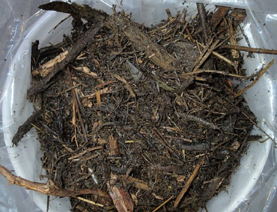
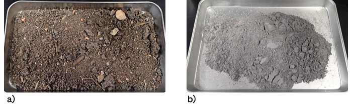
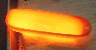
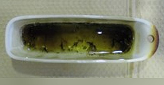
In East Japan, decontamination works have been progressing since the Fukushima Daiichi Nuclear Power Plant Accident to remove radiocesium (r-Cs) widely released by the accident. In March 2018, the works were completed in the target areas except for the Difficult-to-Return Areas1. In the designated Contaminated-Waste Management Areas1 in Fukushima Prefecture, a large amount of “decontamination wastes (DW),” such as grasses, fallen leaves, twigs and excavated soils, have been generated during the decontamination works. Among them, combustible items (Fig. 1) have been incinerated at temporary treatment plants that were installed in each municipality to reduce waste volume. The volume decreases considerably through the incineration processes, but incineration residues called “bottom ash” and dust (fine particles in flue gas) called “fly ash” (Fig. 2a and 2b) are generated. They have been transported into and kept at the Interim Storage Facility (ISF). Since April 2020, these ashes have been melted at two temporary ash treatment plants. More precisely, at these plants, they are processed by high-temperature heat-treatment at more than 1,300℃ and turned into magma-like liquid (melted material) (Fig. 3). Then, it is cooled rapidly with water to make a glass-like solid state material called “slag” (Fig. 4). ISF also has shaft-type melting furnaces on the same premises2.
If the concentrations of r-Cs in slag are sufficiently low, it can be recycled into roadbed materials and feedstock for cement. For this reason, the temporary ash treatment plants separate r-Cs as gases by adding chemicals, and significantly reduce the r-Cs concentrations in slag. The gaseous r-Cs compounds that have migrated to flue gas become solidified on the surfaces of fly ash during the cooling of the flue gas. Fly ash containing r-Cs compounds is collected using a flue gas treatment unit called baghouse. As r-Cs compounds are highly concentrated in fly ash, it is confined in rectangular steel containers and kept in ISF whose walls for radiation protection are more than 30 cm thick3. In addition to such exposure prevention measures, secure storage and control are ensured for fly ash containers through monitoring their air dose rates and concentrations in groundwater.
Challenges for safe operation of ash melting treatment
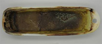
In one ash melting treatment plant at ISF, calcium oxide (CaO) and calcium chloride (CaCl2) are added to bottom ash and fly ash as agents. The calcium (Ca) content in ash is related to the ash melting temperature while chlorine (Cl) content is related to a process of evaporating r-Cs as its chloride (r-CsCl) gases resulting in lowering the r-Cs concentration in the melted material. The ash with high Ca content does not easily melt with this treatment, even if it is heated to 1,400℃. It rather becomes hard aggregates of ash particles as shown in Fig. 5a. If you refer to the phase diagram of three major components of ash, namely CaO, alumina (Al2O3) and silica (SiO2), you can see that the ash melting temperature increases as weight ratio of CaO to SiO2 increases.
As for the Cl, the melting treatment of ash with high Cl content produces two different materials. One is the slag shown in Fig. 4 and the other is white solid-state material (Fig. 5b). This white material is a kind of salt whose main components are Ca and Cl, and it is easily dissolved in water. It should be noted that, since the white material contains relatively high concentrations of r-Cs, the water that is used for rapidly cooling melted materials becomes contaminated when this white material is generated. For these reasons, the weight ratios of Ca and Cl to Si in ashes need to be well controlled before melting treatment.

If the state of bottom ash and fly ash transported into temporary ash treatment plants is always constant, a fixed amount of two Ca-based chemical agents can be added to them. However, the ratios of chemical elements (i.e., elemental compositions) in the ashes change from day to day. This is because the wastes consist of a variety of materials such as grasses, fallen twigs and soils adhering to them, and because they are sometimes incinerated with other disaster wastes at temporary treatment plants. Our previous surveys found that the elemental compositions of fly ash, in particular, fluctuate significantly4. In our laboratory experiment of melting treatment, we have been investigating the range of elemental compositions that enables the production of homogeneous slag without the white material by adjusting the amounts of the chemical agents to add and altering the elemental compositions of Ca, Cl and Si. We have also been examining the r-Cs concentrations in the slag to clarify the range of elemental compositions that minimizes them and produces no white material. In other words, we have been clarifying the elemental composition conditions suitable for ash melting treatment.
In order to determine the amounts of chemical agents to add, it is necessary to know the compositions of Ca, Cl and Si for bottom ash and fly ash respectively as accurately as possible. As a means to detect them accurately, there is a method that uses acid treatment to dissolve these elements from ashes in sample solution and analyzes them. However, this method is a time-consuming work. Therefore, we have also been examining various other methods that can be applied to analyze the elements quickly and accurately. For example, we have been developing a method that uses fluorescent x-rays, not acid treatment, to analyze elemental compositions. We have also been tackling problems related to this method. In particular, analysis of samples with a small amount of Si may not always lead to correct results, and we have been solving this problem by improving pretreatment of samples5. By developing a method that can determine both compositions of chemical elements suitable for ash melting treatment as well as actual contents of elements in ashes, more flexible melting operation will become realized for the ashes of different compositions. It will also lead to more stable ash melting treatment.
Lastly, there is one more issue to be solved in ash melting treatment. Since it generates fly ash with a high concentration of r-Cs, a large space is required for its storage and subsequent treatment processes. In view of this, some additional processes to reduce fly ash volume have been studied in our research division. If they are implemented, its volume to store and manage may be significantly minimized.
References
- Ministry of the Environment, Japan http://shiteihaiki.env.go.jp/radiological_contaminated_waste/regional_measures/ (external link, in Japanese language only)
- Noda et al. (2020) Process Safety and Environmental Protection, 143, 186-195
- Ministry of the Environment, Japan http://josen.env.go.jp/chukanchozou/action/safety_commission/pdf/safety_commission_07_190327.pdf (external link, in Japanese language only)
- Kuramochi et al. (2018) Proceedings of the 7th Annual Meeting of the Society for Remediation of Radioactive Contamination in the Environment, 38
- Noda et al. (2019) Proceedings of the 8th Annual Meeting of the Society for Remediation of Radioactive Contamination in the Environment, 27