

- Waste management in Japan
- Circular economy in Japan
- Waste management in Asia
- Disaster waste management
Waste-to-Methane Fermentation Unit Made from Polyethylene Tube
Methane fermentation unit made from polyethylene tube
Our article in the May 2012 issue introduced a simple low-cost methane fermentation unit made from polyethylene (PE) tube that can provide farmers in developing countries in Asia and elsewhere with a self-sufficient means of obtaining fuel gas for cooking and other purposes from organic wastes. Similar handmade fermentation units have been used worldwide as their operation requires neither fuel nor electricity. Among many types of methane fermentation units, the simplest and least expensive type is the one made from PE tube. This article will introduce this type of unit, and how to install it in the field.
PE tube size and creation of foundation
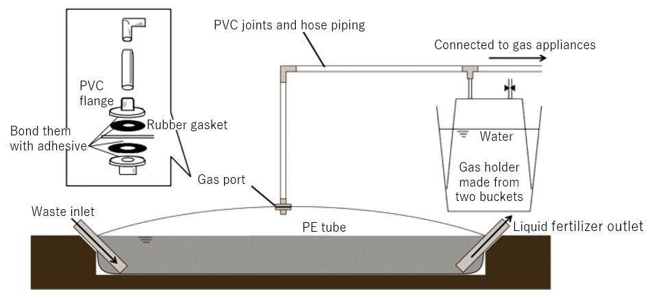
Figure 1 shows an overview of the methane fermentation unit made from PE tube. PE tube is a tube made of thin polyethylene usually with a thickness of about 0.06 mm. It looks like a big plastic bag with no closed end. As its shape is unstable, the first process for making the unit is to dig a pit in the ground to install the entire PE tube inside it. The size of the pit is determined according to that of the unit which depends on the amount of inputs to be processed. For example, about 5 m3 PE tube unit would be suitable to process 20 kg of cow manure every day to produce about 0.5 m3 of methane per day in summer. For details of the calculation of the unit volume requirement and expected amount of methane gas generation, please refer to the reference materials listed at the end of this article.
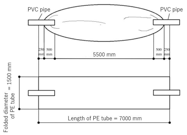
While various PE tube products in different diameters are available, the unit explained in this article uses a polytube of 1.5 m in folded diameter (1 m in diameter) to make a 5 m3 unit. The required PE tube length is shown in Fig.2. The total length should include a margin of about 0.75 m at each end to be used to fix inlet or outlet pipes. The cross-sectional area of the tube is 0.79 m2 whose 80-90% is that of the pit. A part of the tube's volume (10-20%) that exceeds the pit volume allows the gas to accumulate inside. In our case, the cross section of the pit is calculated to have 0.8 m width and 0.8 m depth. The required PE tube length, therefore, is: 5 / (0.8 x 0.8) + 1.5 = 9.3 m. The length of the pit is: 5 / (0.8 x 0.8) = 7.8 m. With these dimensions, the first step is to dig a pit of 0.8 m (width) x 0.8 m (depth) x 7.8 m (length). Then, the second step is to make an additional hole at one end of the tube for inserting an inlet pipe and to make another at the other end for an outlet pipe. Both holes need to be set to the same diameter as the pipes and tilted at a slope of 45 degrees.
Preparation of PE tube
To increase strength, use two or more PE tubes in layers. When the required number and length of PE tubes are obtained, the first item to attach to them is a gas outlet port. Make a hole in the PE tube to attach a polyvinyl chloride (PVC) flange and a rubber gasket from either side of the PE tube as shown in Fig.1. Next, insert PVC pipes at both ends of the tube; one is used as inlet and the other is used as outlet. Use the margin at each end (Fig.2) to wrap around the pipe. Then, roll rubber wind tube around it firmly to prevent leakage of gas and liquid. When these processes are completed, install the PE tube inside the pit.
Preparation of other parts
Make a gas holder by stacking two plastic buckets of 400-500 L capacity (Fig.1). Fill one bucket with water and allow the other bucket to float in it upside down. Open a hole in the bottom of the floating bucket to insert a rubber hose to be connected to a gas conduit to supply generated gas. To prevent gas leakage, seal the gap between the hole and the hose with adhesive putty. The water in the bucket not only holds the gas but also absorbs hydrogen sulfide. The water therefore should be replaced regularly.
For the gas piping, use either hoses or PVC pipes or combination of both as appropriate. Tighten all the connections with hose clamps or similar products to prevent gas leakage. The end of the gas piping can be connected to various gas appliances including gas burner cooking stoves and ~1kW small power generators. As the low-calorie gas generated in the fermentation unit cannot be used for the cooking stoves commonly available in Japan, a stove also needs to be handmade in Japan for the above-mentioned usage. Please refer to the reference materials for details.
Start-up of the unit and charging of raw material
Choose relatively warmer months to start up the unit's operation because in colder months, it takes longer for microorganisms to contribute to fermentation process due to their inadequate activity. Before charging raw materials such as cow manure, increase the number of anaerobic microorganisms that decompose organic matter and generate methane. For this purpose, fill the PE tube with a small number of inoculum microorganisms (20-50%) and water. This process facilitates the start of fermentation. Here, the materials that can provide the inoculum microorganisms are sludge, cow manure, compost, and river/lake sediments. Then, add one or two-day raw materials to the inoculum microorganisms. Necessary microorganisms grow for a month or two until fermentation stops. Add new raw materials only after it stops. The best way to judge fermentation stability is to examine pH value of liquid samples taken from the area around the inlet pipe in the tube. If they show neutral pH, it means that fermentation is stable. The key to stable operation is to charge constant amount of raw materials every day. With stable operation, the unit can supply constant amount of gas every day.
For more information
- Kobayashi T., Xu K. et al. (2011) Current situation of household biogas plants in rural area of China, Journal of water and waste, 53 (9), 707-717
- An B.X., Preston T.R. et al. (1997) The introduction of low-cost polyethylene tube biodigesters on small scale farms in Vietnam. Livestock Research for Rural Development (9) 2. (http://www.fao.org/docrep/w5256t/w5256t06.htm)
- Van Buren A. (1998) A Chinese Biogas Manual: Popularising Technology in the Countryside, 136pp. Practical Action Publishing, UK.